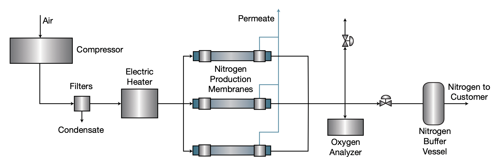
Membrane nitrogen separation became commercially available in the early 1980s. It is the most robust of the nitrogen separation technologies. Compared to Pressure Swing Adsorption (PSA) technology, membranes use more energy when operate at higher purity, but have lower maintenance costs. Membranes are best suited for purities from 95% up to approximately 99.5% and nitrogen demand of up to around 2,000 Nm³/hr.
The membrane consists of a bundle of selectively permeable hollow fibers. It separates nitrogen from atmosphere by passing compressed air through the side wall of hollow polymer fibres. The process relies on the principle of selective gas permeation. Each gas has a different permeation rate, so as the compressed feed air stream passes across the membrane, gases with faster permeation rates like oxygen, carbon dioxide, and water vapor are released back into the atmosphere as waste gas (along with some nitrogen). The product nitrogen, now stripped of most of the oxygen and carbon dioxide, passes out the other end of the separator at a slightly lower pressure for collection or directly into your application.
Nitrogen gas purity increases as the flow proceeds down the fibres. Depending on the residence time in the membrane, nitrogen purity of better than 99.5% can be achieved. If the application require higher purity levels, PSA technologies are the solution more cost-effective.
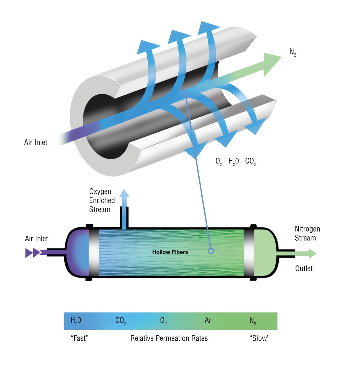
The module body has one inlet pipe for feed gas mixture intake, and two outlet pipes for delivery
Highly permeating gases (e.g. H2, CO2, O2, water vapors, higher hydrocarbons) penetrate the fibers and exit the membrane cartridge through one of the pipes. Less permeating gases (e.g. CO, N2, CH4) exit the membrane modules through the other outlet pipe.